


 +86-317-8227664
 Annie@saikenpumps.com

The KCB gear pump ensures a constant flow to the die at both pressure and speed. In many production processes, the inlet pressure is high and the outlet pressure is low. The purpose of establishing a high back pressure to the extruder is to enhance mixing and melting, while the flow through the die is regulated by the pump to achieve a final product size. On the extrusion line with gear pump assistance, since the inlet pressure of the KCB gear pump is kept low (usually 500 psi), the material is returned during the pressure transfer from the screw of the extruder to the gear pump. Can be reduced from a hydraulic point of view, KCB gear pump is a device that is more effective than the extruder to establish pressure. Thus, the output of the screw extruder at a given die pressure can be greatly improved. For the gear pump gasket replacement, it is a key issue to ensure the long-term stable operation of the gear pump product.
KCB gear pump operation and maintenance methods are:
1. The initial start should be to inject the liquid into the pump.
2. Check all pipe flanges and seals of the joints before starting.
3, the initial start should be injected into the pump to deliver liquid. Drive the coupling without friction and collision sound.
4. The valve in the suction and discharge lines should be fully opened before starting. It is forbidden to start the valve.
5. After verifying the direction of rotation of the motor, start the motor.
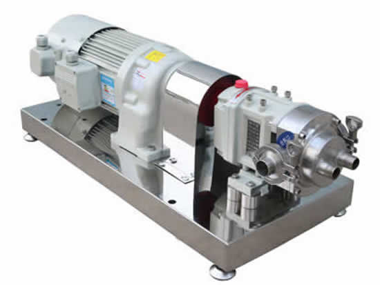
KCB gear pump is a pump with reliable structure, stable operation and low cost. It can transport non-corrosive oil and other viscous media. Moreover, the gear pump itself has a valve, the conveying medium is high, and the gear pump relies on Its outstanding performance and adaptability have been widely used. The influence of the flange surface roughness of the gear pump. The surface roughness of the flange has a great influence on the sealing effect, especially when the non-soft gasket is used, the degree of roughness of the sealing surface is one of the main causes of leakage. For example, the blade of the turning flange surface is a spiral. When the metal gasket is used, if the roughness value is large, the gasket can not block the spiral groove formed by the blade. Under the action of pressure, the medium will be under pressure. Leak along this groove. The soft gasket requires a much lower level of smoothness on the flange surface because it is easily deformed and can block the machining of the knives, thus preventing leakage. For soft gaskets, the flange surface is too smooth and unfavorable because the interface leakage resistance becomes smaller at this time. Therefore, the gasket surface roughness is different for the different gaskets.
1. Repair of the working plane of the gear pump cover
If the working plane of the pump cover is less worn, the wear marks can be removed by manual grinding, that is, a small amount of valve sand is placed on the platform or thick glass plate, and then the pump cover is placed on it for grinding until the wear marks are eliminated and the working surface is flat. . When the working plane of the pump cover wears more than 0.1 mm, it should be repaired by turning and grinding first.
2. Repair of the inner cavity of the gear pump casing
After the inner cavity of the KCB heat preservation gear pump casing is worn, it is generally repaired by the inner cavity inserting method, that is, the inner cavity is enlarged and then cast with cast iron or steel bushing. It should be noted that the gear pump is not suitable for conveying liquids containing solid particles and liquids with high volatility and low flash point; the gears in the gear pump are prone to wear during long-term operation, and the flow rate of the conveying medium is small.
In the gear pump, a pair of meshing gears with the same number of teeth are installed inside the casing, and both end faces of the gear are sealed by the end caps, so that the two gears are divided into left and right sealed oil chambers in the inner cavity of the casing. And a sealed working volume is formed between each tooth. When the gear rotates in the direction shown, the gears are retracted from the right side to expose the teeth, so that the volume of the cavity is increased to form a vacuum. The oil in the oil tank is sucked by the hydraulic pump under the action of atmospheric pressure. The tube enters the right chamber (suction chamber) and completes the oil absorption process. As the gear rotates, the oil is transferred from the right chamber to the left chamber between the teeth of each tooth. The teeth are engaged in the left cavity, and the teeth are occupied by the teeth of the other side, so the volume is reduced, the oil in the teeth is gradually squeezed out, the oil pressure in the left chamber is raised, and the oil is discharged from the oil. The mouth output is completed, and the left chamber is the pumping chamber of the pump. The two gears rotate continuously, and the suction port and the oil discharge port of the pump continuously suck and drain oil, so that the pump continuously supplies oil to the system. From the point of view of energy conversion, the gear pump is the device that completes the initial energy conversion of the system, that is, converts the mechanical energy output by the motor into the hydraulic energy of the oil.


 +8617731766260/15094407290
 +86-317-8227664
 +8615094407290